Oral Presentation International Solvent Extraction Conference 2025
Euler-Euler two-phase CFD model to predict flooding in pulsed disc and doughnut column (122672)
Introduction
Air-pulsed columns are differential contactors having applications in nuclear, pharmaceutical and metallurgical industries. Absence of moving parts make them robust and maintenance-free. Hydrodynamics in an air-pulsed column is dependent on the type of plate internals used in the column. Conventional plates used are sieve plates and disc & doughnut plates. Most of the reported two-phase CFD studies on air-pulsed columns focus on estimation of dispersed phase holdup, drop diameter, drop size distribution and axial dispersion in the column.1,2 However, there are very limited studies to predict flooding throughputs in such columns. This work focuses on development of a CFD model to predict flooding throughputs in pulsed disc & doughnut column (PDDC). The model is validated with reported experimental data.
Computational domain and methodology
In the present work, a 2D axisymmetric CFD model is used to predict the flooding velocities in PDDC. The internal diameter of the column is 76 mm. The inter-plate spacing and % opening area are 10 mm and 23.5%, respectively. Water is taken as the continuous phase and toluene as the dispersed phase. Euler-Euler two-fluid model is used to predict the flooding in the column. Conservation equations of mass and momentum for the two phases coupled with conservation equations for turbulence variables are solved. Standard mixture k-ε model is used as the closure law. Ishii-Zuber drag model is used to estimate the drag force.3 Assumption of monodispersed drop diameter of dispersed phase has been considered in the model. Normal continuous phase velocity and normal dispersed phase velocity boundary conditions are applied at the inlet of continuous and dispersed phase, respectively. At the pulsing velocity inlet, a sinusoidal function of velocity is applied as the boundary condition. The model is validated with the reported experimental data of flooding in PDDC.4
Validation
In CFD model, flooding is considered when the interface between the two-phases moves below the dispersed phase inlet after carrying out simulation for sufficiently long time. On the other hand, a stable interface position above the dispersed phase inlet is considered as the non-flooding condition. As shown in Figure 1, flooding is observed at pulsing velocity, continuous and dispersed phase throughput of 3 cm/s, 56 L/h and 41 L/h, respectively. However, for dispersed phase throughput of 31 L/h and 21 L/h at the same pulsing velocity and continuous phase throughput flooding does not occur. These conditions of flooding and non-flooding obtained from CFD model match with the experimentally reported flooding and non-flooding conditions.4 Thus, it is concluded that the CFD model is capable of predicting flooding in the column. The drop diameter for each operating condition is obtained from the correlation reported in the same study.4 The model also predicts flooding conditions at pulsing velocities as shown in Figure 2(a) which also matches with the experimentally reported flooding conditions.
Results and discussion
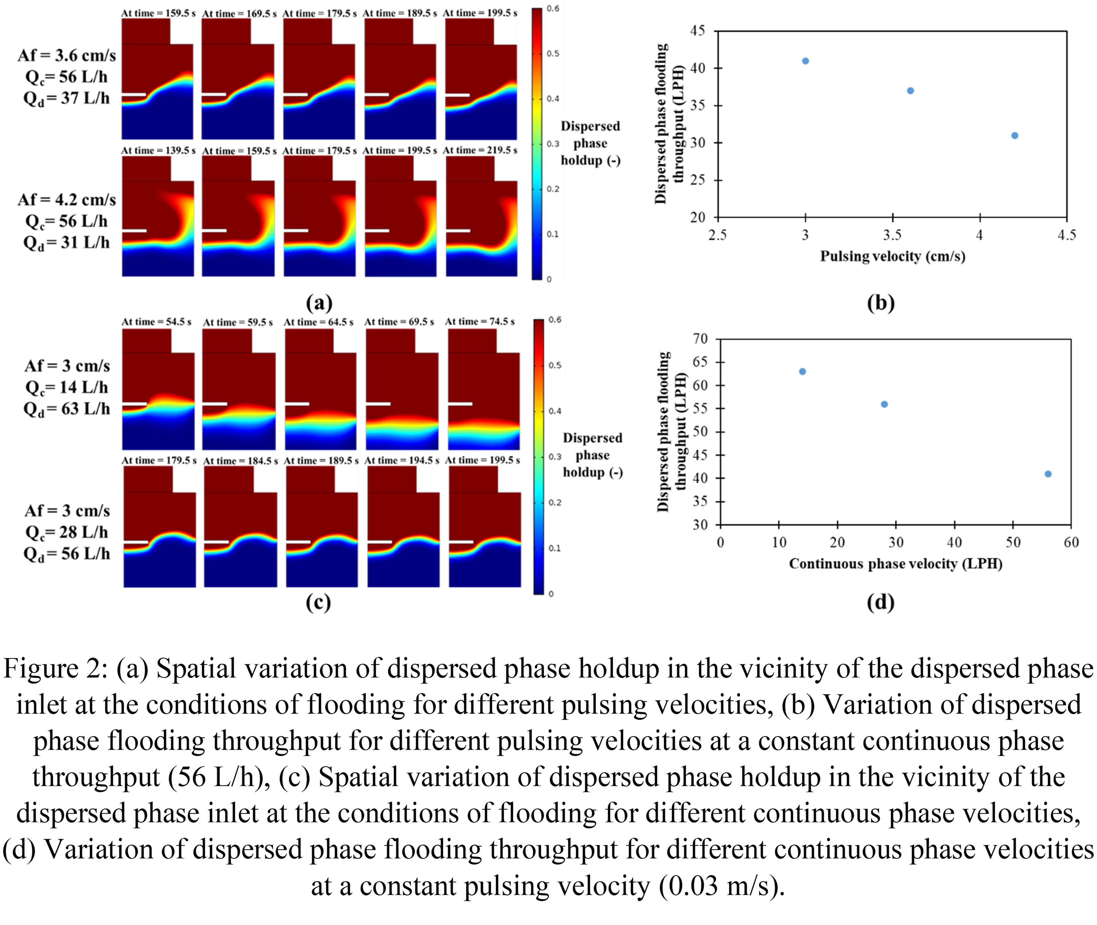
Figure 2(a) shows the dispersed phase holdup contour at the condition of flooding for different pulsing velocities. Since the dispersed phase is the light phase, it should not accumulate below its inlet and should rise through the active section of the column. However, the accumulation of dispersed phase in the bottom disengagement section below its inlet shows the condition of flooding in the column. Increase in pulsing velocity in the column leads to decrease in dispersed phase flooding throughput as shown in Figure 2(b). An increase in pulsing velocity induces more turbulence in the column, thus, forming smaller dispersed phase droplets. These droplets having less terminal rising velocity as compared to the continuous phase velocity start to accumulate in the bottom disengagement section of the column below the dispersed phase inlet. Thus, at higher pulsing velocity, formation of smaller droplets which leads to early flooding at lower throughput.
Figure 2(c) shows the dispersed phase holdup contour at the condition of flooding for different continuous phase velocities. The accumulation of dispersed phase in the bottom disengagement is clearly observed in the contours confirming the condition of flooding. Figure 2(d) shows that an increase in continuous phase velocity decreases the dispersed phase flooding throughput. Higher drag force on the droplets at higher continuous phase velocities prevent them from rising causing them to accumulate in the lower disengagement section at lower throughputs which leads to flooding.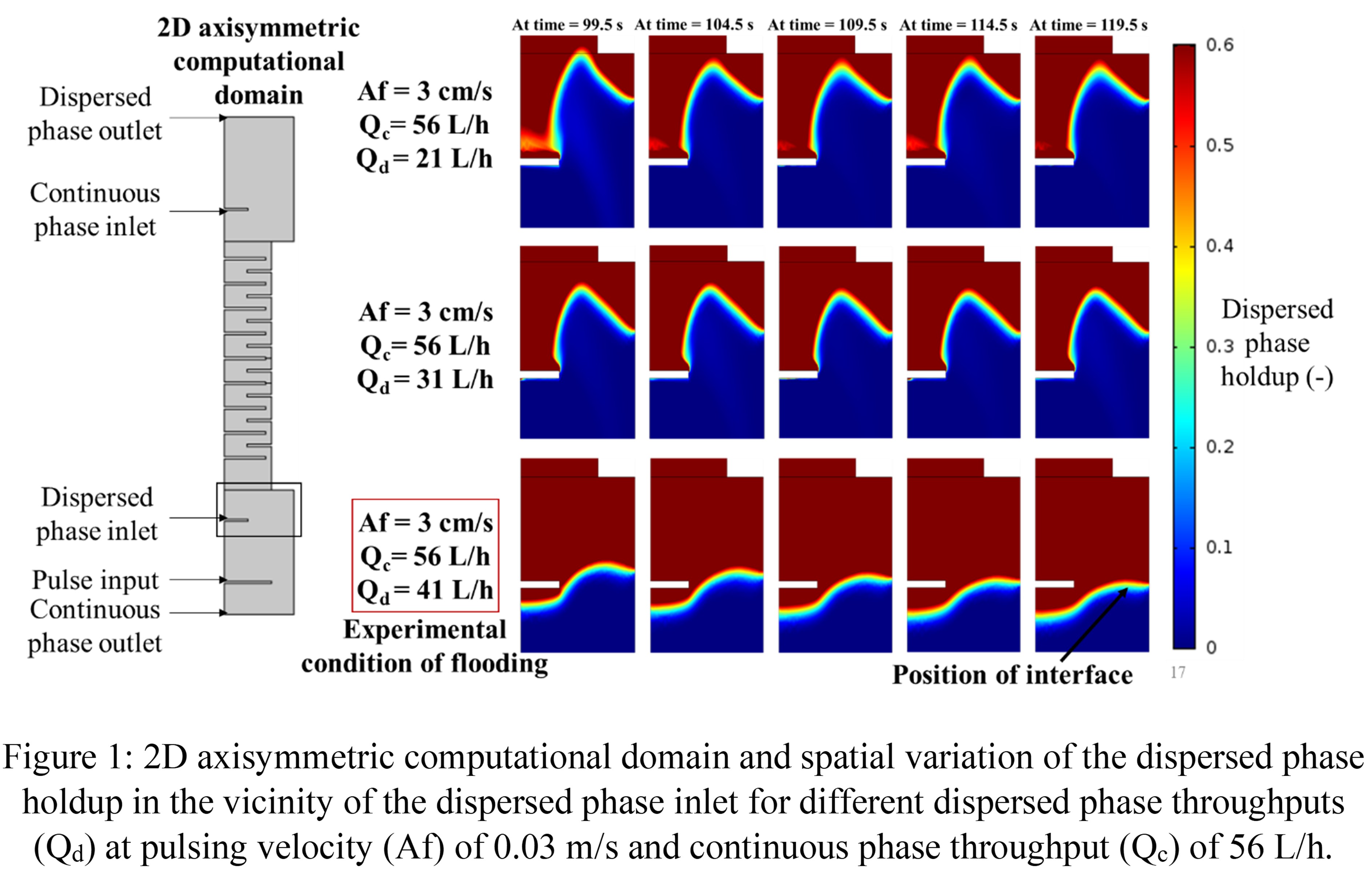
- Sarkar, S., Singh, K. K., & Shenoy, K. T. (2019). Two-phase CFD modeling of pulsed disc and doughnut column: Prediction of dispersed phase holdup. Separation and Purification Technology, 209, 608–622.
- Sen, N., Singh, K. K., Patwardhan, A. W., Mukhopadhyay, S., & Shenoy, K. T. (2018). CFD-PBM simulations of a pulsed sieve plate column. Progress in Nuclear Energy, 111, 125–137.
- Ishii, M., & Zuber, N. (1979). Drag coefficient and relative velocity in bubbly, droplet or particulate Flows. AIChE, 25(5), 843–855.
- Torab-Mostaedi, M., Ghaemi, A., & Asadollahzadeh, M. (2011). Flooding and drop size in a pulsed disc and doughnut extraction column. Chemical Engineering Research and Design, 89(12), 2742–2751.
- Abstract category selection: